Discover expert tutorials, buying guides, operational tips, and industry trends on MIG/MAG, Spot welding equipment and air compressors.
A Thyristorised Welding Rectifier converts incoming AC power into controlled DC welding current. It uses thyristors, also called silicon-controlled rectifiers, to regulate when electrical current enters the rectifier circuit. This timing changes the output available to the welding arc. In practical terms, the operator can adjust welding current through a control panel rather than relying on a fixed transformer output.
The machine usually contains a transformer, thyristor bridge, cooling components, control circuitry, and protection devices. Inside the cabinet, heat sinks help manage the temperature created during continuous welding. The output should remain stable while the electrode touches the workpiece, even when arc length changes slightly. That stability matters during structural fabrication, repair work, and heavy plate welding. Less spatter can also mean less cleaning after the weld.
It is a robust design.
Compared with older magnetic-control rectifiers, thyristor control offers faster and more precise adjustment. However, it is not automatically better for every workshop. Its electronics require suitable cooling, careful inspection, and qualified servicing. Dust, loose connections, and excessive heat can reduce performance over time. A damaged control board may stop the machine completely, although the transformer remains intact. This detail is sometimes overlooked.
Understanding how a Thyristorised Welding Rectifier works helps users select suitable current ranges, duty cycles, and maintenance practices. Manufacturer data remains essential, because designs differ in control response and protection features. The technology is dependable when correctly specified and maintained. Still, real welding results depend on more than the rectifier alone. Electrode choice, grounding, operator technique, and material condition all influence the final bead.
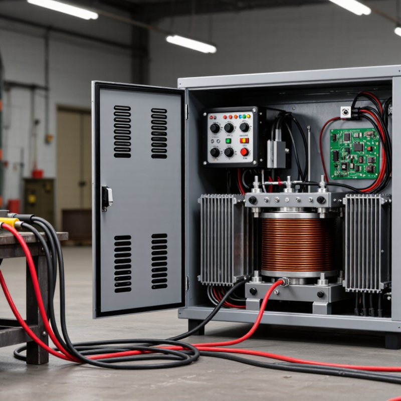
What Is a Thyristorised Welding Rectifier?
A thyristorised welding rectifier converts alternating current into controlled direct current for arc welding. Its main switching devices are thyristors, also called silicon-controlled rectifiers. By adjusting their firing angle, the circuit controls how much electrical energy reaches the welding transformer and rectifier stage.
This design gives operators practical control over welding current and voltage. A stable output helps maintain a smoother arc, especially during long welds or changing electrode conditions. In a workshop, the difference can be felt when the arc starts cleanly instead of sticking or sputtering. The machine normally includes a transformer, control board, cooling system, and output smoothing components. Protection against overheating and excessive current is also essential.
I have found that setup still matters. Clean connections, suitable cables, and correct polarity can affect the arc more than expected. A thyristorised unit is not automatically perfect. Poor calibration may cause delayed response or uneven current. That detail is easy to overlook. Regular inspection should include terminals, cooling passages, control signals, and output readings. Meters can be useful, but an experienced technician should compare them with the actual arc behavior. Small irregularities may indicate wear, loose wiring, or a control fault. Some older systems are durable, yet their electronics deserve careful testing before replacement decisions are made.
A thyristorised welding rectifier converts incoming AC power into controlled DC welding current. Its main parts include a transformer, a thyristor bridge, control electronics, smoothing inductors, and cooling components. The transformer reduces voltage and increases available current for the welding circuit.
The thyristors act as fast electronic switches. During each AC cycle, the control circuit sends a gate pulse to selected thyristors. The firing angle decides when they conduct. Earlier firing produces a higher average DC output, while delayed firing reduces it. This process controls welding current without relying on mechanical contacts. Current sensors measure the output continuously. The controller then adjusts the firing pulses when arc length, electrode movement, or workpiece conditions change.
The arc still fluctuates.
In practical workshop testing, the output rarely behaves like a perfectly flat line. Inductance smooths the current, but some ripple remains. A stable arc depends on correct feedback, clean connections, proper cooling, and accurate calibration. Loose terminals can create heat and unstable welding. Dust around cooling paths may cause thermal protection to activate unexpectedly. A simple explanation can mislead, because transformer losses, commutation effects, and control delays also influence the result. Older rectifiers may respond more slowly than modern switching equipment, yet their heavy transformers and straightforward controls can be easier to inspect and repair.
What Is a Thyristorised Welding Rectifier?
Main Components and Control Principles
A thyristorised welding rectifier converts three-phase AC into controlled DC. Its power path usually includes an input transformer, thyristor bridge, smoothing reactor, and output terminals. The transformer lowers voltage and provides electrical isolation. The thyristor bridge regulates current through firing-angle control. A smoothing reactor reduces ripple and steadies the welding arc.
Control begins with a reference signal from the current or voltage setting. A firing circuit then sends gate pulses to the thyristors. Earlier pulses increase average output voltage and welding current. Later pulses reduce them. Feedback sensors compare actual output with the selected value. This closed loop helps maintain arc stability when electrode length changes. It is practical, but not perfect. Poor calibration can still create visible arc fluctuation.
IEC 60974-1 defines duty-cycle testing around a ten-minute period. A 60% rating at 300 amperes permits six minutes of welding, followed by four minutes of cooling. This figure matters during site work. The International Energy Agency reports that industry remains one of the largest global energy-consuming sectors, making efficient power control increasingly relevant. A 2024 welding equipment market report also identified automation and electronically controlled power sources as major growth factors. However, market forecasts are not operating instructions. Technicians should verify thermal limits, ventilation, cable size, and actual waveform performance. Small installation details often decide whether the rectifier behaves reliably.
What Is a Thyristorised Welding Rectifier?
A thyristorised welding rectifier converts AC power into controlled DC welding current. Thyristors regulate output by changing their firing angle. This design delivers a steady arc, strong penetration, and adjustable current for demanding work. Operators commonly select a drooping characteristic for stick welding and a flatter response for wire processes. The control feels deliberate, not instant. That slower response can help heavy electrodes, but it may feel less refined than modern inverter equipment.
Welding Characteristics and Common Applications
These rectifiers suit shielded metal arc welding, submerged arc welding, air carbon arc gouging, and some wire-feed systems. Their robust transformers tolerate dust, heat, and long duty cycles. That matters in shipyards, structural fabrication, pipeline workshops, and repair bays. The U.S. Bureau of Labor Statistics reported about 428,300 welding, soldering, and brazing jobs in 2023, with roughly 42,600 annual openings projected over the decade. Those figures reflect continuing demand for dependable industrial power sources.
Power efficiency deserves attention. The International Energy Agency’s Energy Efficiency 2023 report identifies industry as using about 37% of global final energy. Thyristor control can reduce wasted output, yet harmonics and poor power factor may remain. A suitable reactor, balanced phase loading, and regular calibration improve results. It is not perfect. Arc response can lag during rapid current changes, and setup errors still produce spatter or weak fusion. Skilled operators often compensate through inductance, travel speed, and electrode selection.
| Data Dimension | Typical Information | Effect on Welding Performance | Common Applications |
|---|---|---|---|
| Definition | A welding power source that uses thyristors, also called silicon-controlled rectifiers (SCRs), to control and rectify electrical power. | Provides adjustable direct-current welding output with electronic control of the rectifier firing angle. | Industrial manual and semi-automatic arc-welding systems. |
| Input Supply | Commonly supplied from a single-phase or three-phase AC source, typically at 50 or 60 Hz. | Three-phase input generally gives smoother output and better capacity for higher welding currents. | Fabrication shops, maintenance departments, construction sites, and production workshops. |
| Output Type | Controlled DC output, usually delivered through a transformer, SCR bridge, smoothing reactor, and control circuit. | Supports stable arc operation for processes that require direct current. | Shielded metal arc welding, gas metal arc welding, flux-cored arc welding, and submerged arc welding. |
| Current Control | Welding current is regulated by changing the firing angle of the thyristors. | Allows continuous adjustment of output current and helps match heat input to material thickness and electrode size. | General-purpose welding where repeatable current adjustment is required. |
| Typical Current Range | Many industrial units are available from approximately 200 A to more than 1,000 A, depending on design and duty rating. | Higher-rated systems can handle large electrodes, thick sections, and high-deposition welding. | Light fabrication at lower ratings; heavy structural, shipbuilding, pressure-vessel, and pipeline work at higher ratings. |
| Current Adjustment | Usually controlled by a front-panel potentiometer, remote control, or a wire-feed interface. | Makes it possible to set welding parameters without changing transformer taps manually. | Manual welding stations and semi-automatic wire-feed systems. |
| Arc Characteristics | Generally provides a robust, relatively smooth arc, with characteristics influenced by the control circuit, smoothing inductance, and welding process. | Can provide reliable arc starting and good tolerance of variations in electrode contact and arc length. | Stick welding, carbon arc work, and industrial wire welding. |
| Polarity Selection | Many DC welding rectifiers provide electrode-positive and electrode-negative connections. | Allows users to select polarity according to electrode type, penetration requirement, and welding procedure. | Carbon steel, stainless steel, low-alloy steel, and selected nonferrous welding procedures. |
| Dynamic Response | Faster than purely magnetic control but generally slower than modern high-frequency inverter control. | Suitable for conventional welding, although rapid changes in arc length may produce more noticeable current response delay. | Heavy-duty shop welding and applications with relatively steady welding conditions. |
| Duty Cycle | Industrial models commonly use duty ratings such as 60% or 100% at a specified ambient temperature and output current. | A higher duty cycle permits longer welding periods before thermal protection or cooling-down time is required. | Continuous production, long weld seams, structural fabrication, and submerged arc welding. |
| Power Efficiency | Typically more efficient and controllable than older magnetic-amplifier systems, but generally less compact than inverter power sources. | Offers a practical balance between controllability, serviceability, and equipment size. | Fixed workshop installations and applications where ruggedness is prioritized over portability. |
| Power Factor and Harmonics | Phase-controlled SCR operation can introduce input current distortion and lower power factor, particularly at reduced output levels. | May require suitable electrical distribution capacity, power-factor correction, or harmonic assessment in large installations. | Industrial plants with dedicated electrical infrastructure. |
| Cooling Method | Most units use forced-air cooling; high-current systems may use enhanced cooling arrangements. | Adequate airflow is essential to maintain rated output and protect thyristors, transformers, and rectifier components. | Indoor workshops and controlled industrial environments. |
| Maintenance Requirements | Periodic inspection may include cleaning, checking cooling fans, tightening electrical connections, and testing SCRs and control boards. | Routine maintenance helps prevent overheating, unstable output, and premature component failure. | Maintenance programs with qualified electrical and welding technicians. |
| Main Advantages and Limitations | Advantages include rugged construction, controllable DC output, and suitability for high-current work. Limitations include greater weight and size than inverters, slower response, and possible input harmonics. | Best suited to demanding, stationary applications where durability and high output are more important than minimum weight. | Heavy fabrication, shipyards, structural steelwork, repair welding, and high-current production operations. |
A thyristorised welding rectifier uses controlled silicon devices to regulate welding current through phase-angle control. Its main advantage is rugged, predictable operation in demanding workshops. Operators can adjust current smoothly for different electrode sizes and plate thicknesses. The transformer-based design also tolerates dust and electrical abuse better than many delicate electronic systems. It is forgiving.
Its limitations deserve equal attention. Thyristor control responds more slowly than modern high-frequency inverters, especially during rapid arc-length changes. It may also produce greater ripple, poorer power factor, and harmonic distortion without suitable correction.
The International Energy Agency reported that industry consumed about 37% of global final energy in 2022, so inefficient welding equipment should not be dismissed as a minor concern. Actual losses depend on loading, cable length, and operator technique. Not always obvious.
Maintenance needs are practical, not glamorous. Keep ventilation paths clear, especially where grinding dust settles on heat sinks and fans. Inspect terminals for discoloration, loose connections, and heat damage during scheduled shutdowns. IEC 60974-1 evaluates duty cycle over a ten-minute period; a 60% rating means six minutes of welding and four minutes of cooling at the stated output.
Exceeding that rating repeatedly can shorten transformer and thyristor life. Service records should include output-current checks, cooling-fan condition, insulation tests, and waveform observations.
A field technician may find stable current but excessive heat, which signals resistance, blocked airflow, or calibration drift. The machine can still weld. That does not mean it is healthy.
It converts alternating current into controlled direct current for arc welding. Thyristors regulate the electrical output. The arc becomes steadier.
A control circuit sends gate pulses to the thyristors. Earlier pulses increase output. Later pulses reduce it. Timing matters greatly.
Common parts include an input transformer, thyristor bridge, smoothing reactor, control board, and cooling system. Output terminals complete the power path. Keep connections clean.
It reduces current ripple after rectification. This helps create a smoother welding arc. Without proper smoothing, the arc may sputter.
Feedback sensors compare actual output with the selected setting. The system adjusts the firing signal when conditions change. It helps, but calibration still matters.
A 60% rating at 300 amperes allows six minutes of welding in ten minutes. The remaining four minutes allow cooling. Do not ignore ventilation.
Check terminals, cables, polarity, cooling passages, control signals, and output readings. Watch for loose wiring or unusual heat. Small faults can grow.
Possible causes include poor calibration, worn components, incorrect polarity, weak connections, or cooling problems. The machine is not automatically perfect. Compare meter readings with actual arc behavior.
A Thyristorised Welding Rectifier is an electrical welding power source that converts incoming AC power into controlled DC output. It uses thyristors, or silicon-controlled rectifiers, to regulate the amount of current delivered to the welding arc. By adjusting the firing angle of these semiconductor devices, the system can provide stable and responsive control over welding current and voltage. Its main components typically include a transformer, thyristor bridge, control circuit, cooling system, and protective devices.
This type of rectifier offers reliable arc performance and is suitable for processes such as shielded metal arc welding and other industrial applications requiring adjustable current. Its advantages include good control, strong overload tolerance, and relatively simple operation. However, it may be heavier and less energy-efficient than modern inverter equipment, while its electronic components require protection from heat, dust, and moisture. Regular inspection, cleaning, cooling-system checks, and testing of electrical connections help maintain safe and consistent performance.