
Engineering Excellence in OEM/ODM Power Transformer Manufacturing
Modern electrical distribution grids, renewable energy integration projects, and heavy industrial plants demand unprecedented operational efficiency, thermal stability, and grid resilience. As a premier global OEM/ODM power transformer supplier, our engineering core leverages over four decades of metallurgical research, electromagnetic calculation models, and advanced automated manufacturing technologies to manufacture power solutions ranging from 10kV distribution units to 66kV utility-scale substations.
Information Gain Insight: Selecting a power transformer requires looking beyond initial capital expenditure (CapEx). Total Cost of Ownership (TCO) is dictated by the transformer's continuous core losses ($P_0$, No-Load Loss) and winding resistance losses ($P_k$, Load Loss) over a typical 30-year operational lifecycle.
1. Core Electromagnetic Engineering & Material Selection
The foundation of electrical efficiency in power transformers lies in minimizing hysteresis and eddy current losses within the magnetic core. Our custom ODM manufacturing processes exclusively utilize high-permeability, grain-oriented silicon steel sheets (CRGO) featuring domain refinement technology. By selecting ultra-thin silicon steel laminations (0.18mm to 0.23mm thickness) stacked using automated 45-degree full-mitred step-lap joint technology, our engineering team achieves up to a 25% reduction in no-load losses and drastically lower excitation current and acoustic noise output compared to conventional core assemblies.
2. Winding Topologies & Thermal Dissipation Physics
Transformer longevity depends entirely on dielectric insulation integrity and heat dissipation efficiency. We implement multi-layer cylindrical, continuous, and helical winding topologies engineered specifically for optimal mechanical strength against electromagnetic short-circuit stresses:
• Oxygen-Free Copper Conductors: All high-voltage (HV) and low-voltage (LV) windings utilize 99.99% high-purity electrolytic copper wrapped in thermally enhanced Kraft paper or high-temperature Nomex aramid insulation.
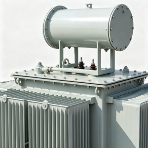
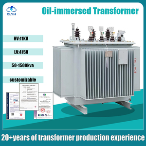
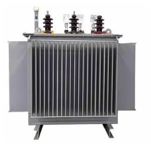
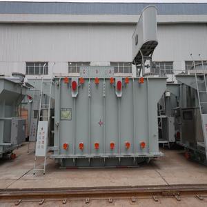
• Directed Oil Flow & Duct Design: In oil-immersed transformers, cooling channels are radially positioned within the winding coils to prevent thermal hot-spots, maintaining dielectric oil temperatures well below oxidation thresholds even during 120% continuous overload conditions.
3. Technical Comparison: Cast Resin Dry-Type vs. Oil-Immersed Transformers
To assist procurement directors, EPC contractors, and electrical engineers in specifying the appropriate unit, the table below delineates key operational parameters across transformer topologies:
| Performance Criterion | Cast Resin Dry-Type (SCB Series) | Oil-Immersed Power (S11/S20/SZ Series) |
|---|---|---|
| Primary Voltage Range | Up to 35 kV | Up to 66 kV / 110 kV / 220 kV |
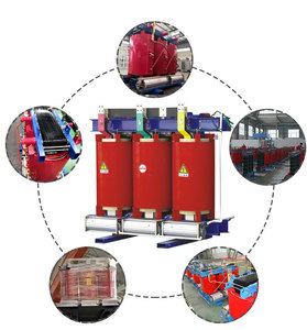
| Cooling Medium | Natural Air (AN) / Forced Air (AF) | Mineral Oil / Synthetic Ester (ONAN/ONAF) |
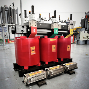
| Fire Safety & Environmental | Class F1 Fire Proof, Self-Extinguishing | Requires Oil Catch Basins & Fire Barriers |
| Maintenance Requirements | Minimal (Periodic Cleaning & Visual Inspection) | Periodic Oil Testing (DGA, Dielectric Breakdown) |
| Partial Discharge Level | < 5 pC (Ultra-Low Noise & Wear) | < 10 pC |
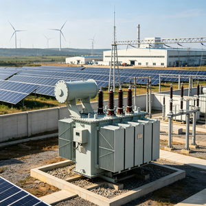
| Target Application Environment | Commercial Towers, Underground Mines, Hospitals | Outdoor Substations, Heavy Industry, Solar/Wind Farms |