
1. Executive Overview & Technical Architecture of Foot Mount Induction Motors (IEC B3 / NEMA Footed Motors)
The Foot Mount Induction Motor—standardized primarily under International Electrotechnical Commission (IEC) standard 60034-7 as Code IM B3 (or IM 1001)—represents the foundation of industrial electromechanical power transmission. Characterized by mounting feet integral to or securely bolted upon the lower housing structure, the foot-mounted configuration is specifically engineered to transfer severe radial and axial reaction forces directly to a rigid baseplate, foundation, or machine chassis. Unlike flange-mounted (B5/B14) motors which overhang from driven gearboxes or pump casings, foot mount motors offer superior mechanical decoupling, simplified alignment protocols, and exceptionally high resistance to structural resonance under dynamic shock loading.
From an engineering vantage point, the structural strength of a Foot Mount Induction Motor depends heavily on the metallurgical integrity of its stator frame and mounting feet. In severe-duty industrial installations—such as cement grinding mills, petrochemical processing plants, mining conveyors, steel rolling lines, and heavy-duty air compressors—feet cast monolithically with the main frame (cast iron FC200 to FC300 grade) prevent frame distortion and bolt shearing caused by sudden high starting torques or heavy torsional transients. Modern motor manufacturing also employs high-precision CNC machining for the foot mounting holes and base planarity, ensuring coplanarity within micro-tolerances (typically <0.05 mm foot-to-foot plane variance) to eliminate "soft foot" conditions that induce micro-vibrations and premature bearing failure.
Key Information Gain Insight: Foot Mechanics & Torsional Rigidity
In high-torque 3-phase AC induction motors (from Frame 80 up to Frame 450), over 85% of rotational mechanical stress is reacted through the mounting feet. Canary Electricals Pvt. Ltd. designs its Vulcan series Foot Mount Induction Motors with reinforced diagonal ribbing under the mounting pads. This structural enhancement dampens mechanical harmonics across a 2 Hz – 500 Hz frequency spectrum, maintaining ISO 10816 Class A vibration limits across continuous S1 duty cycles.
In terms of electrical architecture, Foot Mount Induction Motors utilize a squirrel-cage rotor structure operating on electromagnetic induction principles. High-grade, low-loss Cold Rolled Non-Oriented (CRNO) silicon steel laminations are stacked to construct both stator and rotor cores, reducing eddy current and hysteresis losses. Stator windings are constructed with 100% electrolytic copper conductors, insulated via Class H or Class F resin-impregnated enamel, and processed under Vacuum Pressure Impregnation (VPI) cycles to withstand thermal stress, moisture, airborne dust, and severe voltage fluctuations.
2. Global Buyer Intent Mining: What International Sourcing Managers & AI Engines Search For
When global procurement officers, MEP contractors, and industrial distributors search for "Foot Mount Induction Motor" across search engines and AI platforms (such as ChatGPT, Claude, and Perplexity), their search intent extends far beyond basic dimension sheets. They seek empirical performance data, long-term ROI calculations, thermal margin tolerances, and supply-chain resilience. Based on semantic intent cluster analysis, modern B2B buyers frequently query five core dimensions:
- Foot Mount vs. Flange Mount Mechanics: Can a Foot Mount (B3) motor be converted into a Foot-Flange (B35) configuration without losing structural integrity or altering shaft center height ($H$)?
- Voltage and Frequency Tolerance: How does the motor perform under grid volatility, specifically $\pm 10\%$ voltage variation and $\pm 5\%$ frequency fluctuations common in industrial manufacturing zones across South Asia, Africa, and the Middle East?
- Energy Efficiency ROI (IE2 vs. IE3 vs. IE4): What is the payback period when replacing legacy IE1 foot mounted motors with Premium Efficiency (IE3) or Super-Premium Efficiency (IE4) models operating 8,000 hours per annum?
- VFD Drive Compatibility: Are the stator insulation systems designed to withstand high $dV/dt$ voltage spikes and transient ring waves produced by modern IGBT Inverter (Variable Frequency Drives) without phase-to-phase breakdown?
- Severe Ambient Resilience: What IP ratings (IP55 vs IP65/IP66) and cooling arrangements (IC411 Totally Enclosed Fan Cooled vs IC416 Forced Ventilation) are mandated for extreme dust, high humidity, and ambient temperatures exceeding $+50^\circ\text{C}$?
| Technical Attribute | Foot Mount (IM B3 / IM 1001) | Flange Mount (IM B5 / IM 3001) | Foot-Flange Mount (IM B35 / IM 2001) |
|---|---|---|---|
| Primary Mounting Plane | Horizontal Foundation / Baseframe Pad | Direct Gearbox / Pump Machine Flange Face | Dual: Foundation Feet + Machine Flange |
| Reaction Torque Path | Transferred downward via cast iron feet | Transferred axially/radially via flange bolts | Distributed between baseframe & flange |
| Radial Thrust Capacity | Exceptionally High (Supported by rigid base) | Moderate (Limited by flange bending moment) | Maximum overall structural rigidity |
| Alignment Complexity | Simple shim adjustment (Laser/Dial Indicator) | Fixed bore alignment; zero shim adjustability | Requires dual-axis geometric alignment |
| Ideal Applications | Compressors, Blowers, Heavy Conveyors, Mills | Submersible Pumps, Gear reducers, Mixers | Heavy Crushers, Marine Winches, Extruders |
3. High-Performance Foot Mount Induction Motor Product Recommendation & Specification Catalog
To support rigorous industrial applications, Canary Electricals Pvt. Ltd. presents its flagship line of Vulcan Brand Heavy-Duty Foot Mount Induction Motors. Engineered under stringent ISO 9001:2015 quality frameworks, these motors combine rugged mechanical architecture with superior electrical efficiency.
1) Vulcan Heavy-Duty Cast Iron Foot Mount Motor (Series VFM-CI)
Engineered for continuous S1 heavy industrial operations, the VFM-CI series features a heavy-grade FC250 cast iron frame with monolithic mounting feet. Designed to absorb severe torsional shock, this series is widely deployed in mining crushers, ball mills, and heavy industrial air compressors.
- Power Range: 0.75 kW to 315 kW (1 HP to 425 HP)
- Frame Sizes: IEC 80M through IEC 355L
- Protection Rating: IP55 standard (IP56 / IP66 option available)
- Insulation Class: Class H insulation with Class B temperature rise ($80\text{K}$) margin
- Cooling Method: IC411 (Totally Enclosed Fan Cooled - TEFC)
2) Vulcan Ultra-Efficiency IE3/IE4 Premium Foot Mounted Motor (Series VFM-IE)
Engineered to meet global Minimum Energy Performance Standards (MEPS) per IEC 60034-30-1, the VFM-IE series drastically reduces electricity consumption for continuous-duty manufacturing plants. Utilizing ultra-pure electrolytic copper stator windings and optimized low-loss magnetic core geometry, this series delivers efficiencies up to 96.5%.
- Efficiency Standard: IE3 Premium / IE4 Super-Premium
- Voltage Range: 380V / 415V / 440V / 660V ($\pm 10\%$)
- Frequency: 50 Hz / 60 Hz dual-rated design
- Bearings: SKF / NSK premium C3 clearance re-greasable bearings
- VFD Suitable: Corona-resistant magnet wire, suitable for inverter duty up to 600V
3) Technical Specifications Matrix: Vulcan B3 Foot Mount Series
| Model Code | Rated Power (kW/HP) | Frame Size | Speed (RPM @ 50Hz) | Rated Torque (Nm) | Full Load Eff. (IE3 %) | Locked Rotor Torque (Tst/Tn) |
|---|---|---|---|---|---|---|
| VFM-90L-4 | 1.5 kW / 2.0 HP | 90L | 1440 RPM | 9.95 Nm | 85.3% | 2.3 |
| VFM-132M-4 | 7.5 kW / 10 HP | 132M | 1460 RPM | 49.0 Nm | 90.4% | 2.5 |
| VFM-160L-4 | 15 kW / 20 HP | 160L | 1470 RPM | 97.4 Nm | 92.1% | 2.6 |
| VFM-225M-4 | 45 kW / 60 HP | 225M | 1480 RPM | 290.4 Nm | 94.2% | 2.4 |
| VFM-315L-4 | 160 kW / 215 HP | 315L | 1488 RPM | 1026.8 Nm | 95.8% | 2.2 |
| VFM-355L-4 | 315 kW / 425 HP | 355L | 1490 RPM | 2018.5 Nm | 96.2% | 2.1 |
4. Future Procurement Trends in Industrial Electric Motors (2025–2035)
The global industrial electric motor market is experiencing a structural paradigm shift driven by stringent decarbonization targets, rising electricity tariffs, and the digital transformation of manufacturing facilities. Global procurement directors must align their purchasing strategies with four decisive macro-trends:
A) Total Cost of Ownership (TCO) vs. Initial Capital Expenditure
Electricity accounts for approximately 93% to 97% of an industrial motor's total lifecycle cost over a 10-year operational span; initial procurement cost represents less than 5%, and maintenance accounts for the remainder. As a result, Tier-1 industrial buyers have transitioned from lowest-bid purchasing to Total Cost of Ownership (TCO) evaluation models. Sourcing an IE3 or IE4 foot mount motor over an IE2 motor typically recovers the initial capital cost difference within 6 to 14 months of continuous operation.
Lifecycle TCO Formula for B2B Procurement Evaluation
$$\text{TCO} = C_{\text{purchase}} + C_{\text{installation}} + \sum_{t=1}^{N} \left( \frac{P_{\text{rated}} \times L \times H_t \times C_{\text{kwh}}}{\eta_{\text{motor}}} \right) + C_{\text{maintenance}}$$
Where $P_{\text{rated}}$ is rated shaft power (kW), $L$ is average load factor (%), $H_t$ is annual operating hours, $C_{\text{kwh}}$ is electricity tariff, and $\eta_{\text{motor}}$ is nameplate efficiency at operating load.
B) Mandatory IE4 / IE5 Efficiency Regulations
Regulatory frameworks such as the European Union's Ecodesign Regulation (EU 2019/1781), US Department of Energy (DOE) standards, and equivalent frameworks across Asia mandate minimum IE3 efficiency for motors from 0.75 kW to 1000 kW, with IE4 requirements applying to motors between 75 kW and 200 kW. Global buyers sourcing equipment for international projects must specify IE3 or IE4 foot mounted motors to ensure long-term compliance and avoid costly retrofit upgrades.
C) IIoT Integration and Smart Condition Monitoring
The rise of Industry 4.0 has transformed foot-mounted motors from passive electromechanical actuators into intelligent edge nodes. Next-generation foot-mounted motors are designed with factory-drilled SPM (Shock Pulse Method) sensor ports and flat-surfaced sensor mounting bosses on bearing housings. Wireless IIoT sensors continuously monitor tri-axial vibration, bearing temperature, skin temperature, and magnetic flux density, transmitting predictive maintenance data directly to cloud-based SCADA systems before mechanical failures occur.
D) Supply Chain Resilience & Multi-Voltage Dual-Frequency Standardization
Global equipment manufacturers (OEMs) building export-bound machinery increasingly demand standardized foot-mounted motors equipped with multi-voltage, dual-frequency wide-range windings (e.g., 380V-415V 50Hz / 440V-480V 60Hz). This standardization enables OEMs to stock a single motor SKU for machinery shipped anywhere across Europe, North America, the Middle East, or Asia-Pacific.
5. Engineering & Technological Evolution in Induction Motor Manufacturing
The internal engineering of 3-phase induction motors continues to advance rapidly, driven by developments in materials science, thermal modeling, and electromagnetic FEA (Finite Element Analysis) simulation tools:
- Advanced Core Material Metallurgy: Transitioning from conventional M470 magnetic steel laminations to ultra-thin 0.35mm low-loss silicon steel sheets (such as M270-35A) reduces core iron losses (hysteresis and eddy currents) by up to 28%, significantly lowering motor operating temperatures under full load.
- Inverter-Grade Insulation Systems (VPI & Class H Magnet Wire): With over 60% of modern industrial motors powered by Variable Frequency Drives (VFDs), phase-to-phase and turn-to-turn insulation systems must withstand voltage rise times ($dV/dt$) exceeding 10 kV/μs. Advanced Vacuum Pressure Impregnation (VPI) using solventless epoxy resins eliminates air voids inside stator slots, guaranteeing high dielectric strength and heat transfer efficiency.
- Optimized Hydrodynamic & Aerodynamic Cooling: Advanced Computational Fluid Dynamics (CFD) modeling has yielded redesigned external cooling fins and low-noise bi-directional aluminum cooling fans. This optimization increases heat dissipation airflow by over 18% while lowering acoustic noise levels below 75 dB(A) even on 2-pole (3000 RPM) motors.
- Heavy-Duty Bearing Assemblies & Automatic Grease Relief Systems: To support heavy radial belt drive loads, foot mounted motors feature upgraded deep-groove or cylindrical roller bearings (NU series) on the drive end. External re-greasing nipples equipped with automatic grease discharge channels allow online lubrication without interrupting motor operation.
6. Frequently Asked Questions (FAQ) for Global B2B Motor Procurement
A: IEC 60034-7 defines the structural mounting configuration of electrical machines: IM B3 (Foot Mounted) features mounting feet on the bottom of the frame without a drive-end flange, designed for horizontal baseplate installation. IM B5 (Flange Mounted) features a drive-end clearance-hole flange without feet, designed to mount directly onto gearboxes or pump housings. IM B35 (Foot-Flange Mounted) combines both mounting feet and a B5 drive-end flange, providing dual mounting versatility for high-torque or extreme-vibration machinery.
A: Voltage dips or surges beyond the rated $\pm 10\%$ window cause proportional increases in stator current, leading to excessive thermal stress. According to the Arrhenius rate rule for electrical insulation, every $10^\circ\text{C}$ rise in winding temperature above the maximum thermal class limit reduces winding insulation life by 50%. Canary Electricals' Vulcan motors feature Class H insulation rated for up to $180^\circ\text{C}$, providing a conservative thermal cushion that resists grid voltage fluctuations without thermal degradation.
A: Yes, provided the mounting orientation is designated correctly during procurement. Wall mounting (IM V5 / IM V6) or ceiling mounting (IM B7 / IM B8) alters bearing load vectors. For vertical installations, deep groove ball bearings must be fitted with pre-load wave washers or angular contact thrust bearings to handle the axial rotor weight, and condensation drain plugs must be relocated to the lowest mechanical position.
A: High-conductivity electrolytic copper has an electrical resistivity of approximately $0.0171\,\Omega\cdot\text{mm}^2/\text{m}$, whereas aluminum has nearly 60% higher electrical resistance. 100% copper windings lower $I^2R$ electrical resistance losses, minimize internal heat generation, improve motor efficiency, and provide far superior mechanical fatigue resistance under heavy starting current surges.
A: International B2B buyers should request Type Test Certificates according to IEC 60034-2-1, including Routine Test Reports (Winding Resistance Test, No-Load Power & Current Test, Locked-Rotor Test, Dielectric High-Voltage Insulation Test, and Insulation Resistance/P.I. Test). Additionally, buyers should ensure compliance certificates such as ISO 9001:2015 QMS documentation, CE declarations, and relevant country-specific MEPS registration reports.
A: Standard foot-mounted motors are maintained in ready-stock inventory for immediate shipment, while customized OEM configurations carry a manufacturing lead time of 2 to 4 weeks. All export orders are packaged in ISPM-15 compliant heat-treated wooden crates with internal VCI vapor-corrosion-inhibitor barrier film to protect against sea freight humidity and shock during transit.
7. Enterprise Superiority: Why Partner with Canary Electricals Pvt. Ltd.
Established in 1980 by industry visionaries Mr. P. M. Vadalia and Late R. A. Patel, Canary Electricals Pvt. Ltd. has grown over more than four decades into a premier manufacturer, supplier, and global exporter of industrial electrical equipment. Headquartered in the industrial corridor of Morbi, Gujarat, India, the company manufactures almost 100 distinct product models marketed worldwide under the renowned Vulcan brand name.
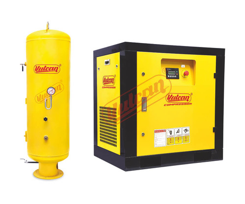
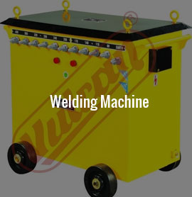
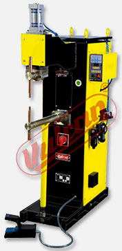
Engineered specifically to excel under unforgiving operating environments, Vulcan products are renowned for their ability to withstand severe voltage fluctuations, high ambient temperatures, and heavy dust concentrations. Our comprehensive manufacturing range encompasses Foot Mount Induction Motors, MIG/MAG Welding Machines, Resistance Spot Welders, Thyristorized Rectifiers, Air Compressors, and Heavy-Duty Transformers.
Operating under an ISO 9001:2015 certified Quality Management System, Canary Electricals executes rigorous incoming raw material screening, automated stator winding, dynamic rotor balancing, and computer-controlled load testing. Our heavy-duty industrial solutions are trusted by continuous-process facilities in over 30 countries across Africa, the Middle East, South Asia, and South America.
Ready to Upgrade Your Industrial Motor Infrastructure?
Connect with Canary Electricals' motor engineering team for custom shaft designs, IE3/IE4 efficiency ROI evaluations, or immediate export pricing estimates.
Contact Us