Resistance Welding Machine: Engineering Authority & Global Procurement Guide
An in-depth technical analysis on Resistance Spot, Seam, and Projection Welding equipment. Written for industrial procurement officers, plant engineers, and global buyers seeking high-efficiency thermal joining solutions.
1. Fundamental Principles & Thermodynamics of Resistance Welding
Resistance welding is a thermo-electric process wherein localized heat is generated at the interface of overlapping metallic workpieces through resistance to electric current flow, combined with applied mechanical pressure. Unlike fusion welding processes such as MIG or TIG, resistance welding requires no filler metals, shielding gases, or flux consumables, making it one of the most cost-effective and environmentally clean mass-production joining methodologies available in modern manufacturing.
The thermal energy generated inside the welding zone is governed by Joule’s Law of Heating:
Joule's Thermal Energy Equation:
Q = I² × R × t
Where Q = Generated heat energy (Joules), I = Secondary welding current (Amperes), R = Total electrical resistance across the electrodes (Ohms), and t = Current flow duration (Seconds / Cycles).
To achieve a structurally sound weld nugget without surface burning or metal expulsion, the total resistance ($R$) must be dynamically managed. Total resistance comprises three distinct electrical components:
Bulk Material Resistance: The intrinsic resistivity of the parent sheet metals being joined.
Electrode-to-Sheet Contact Resistance: The interface contact resistance between the copper alloy electrode tip and the workpiece surface. High contact resistance here causes unwanted surface degradation and premature electrode wear.
Interface (Faying Surface) Resistance: The primary contact resistance between the inner surfaces of the workpieces. This is the crucial location where peak thermal energy must be localized to melt the metal and form a homogeneous molten weld pool (nugget).
Simultaneously, mechanical forging pressure must be exerted by a pneumatic cylinder or servo-motor mechanism. The applied force consolidates the molten nugget, ruptures surface oxide films, prevents internal voids, and contains the liquid metal within the surrounding cold ring until solid-state crystallization completes.
Canary Electricals Pvt. Ltd., establishing industrial engineering benchmarks since 1980 under the leadership of founders Mr. P. M. Vadalia and Late R. A. Patel, manufactures a comprehensive fleet of heavy-duty resistance welders under the Vulcan trademark. Below are our flagship configurations tailored for high-volume enterprise production.
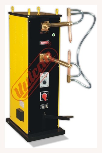
Pneumatic Resistance Spot Welder
Engineered for high-volume automotive and sheet metal fabrication. Features microprocessor-controlled SCR thyristor current timing, water-cooled secondary circuits, and heavy-duty arm throat design.
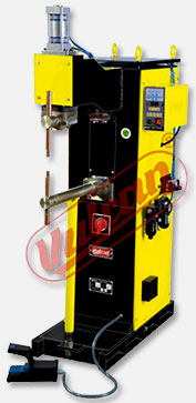
High-rigidity frame design built to handle multiple-embossment projection welding, fastener nut welding, and heavy structural wire mesh assembly without frame deflection.
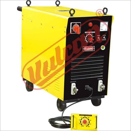
Designed for specialized direct-current resistance heating and continuous heavy-section wire butt welding operations. Exceptional arc stability and precise current ramp control.
Global automotive and metal manufacturing OEMs are undertaking massive re-tooling shifts. Based on global AI search intent data and procurement queries from enterprise buyers in North America, Europe, and Asia, four distinct macro-trends are driving the future of Resistance Welding Machines:
A. Transition from AC Phase Control to Medium Frequency Direct Current (MFDC 1000Hz)
Traditional single-phase AC welders operate at 50/60 Hz line frequency, meaning current drops to zero twice per cycle. This results in longer weld times, higher power spikes, and line imbalance. Modern high-volume lines are rapidly switching to 1000 Hz MFDC technology. MFDC rectifies three-phase input AC into DC, supplying continuous, ripple-free current to the secondary weld transformer.
Energy Savings: Reduces primary power consumption by up to 30–40% while achieving equivalent thermal energy output.
Balanced Mains Load: Distributes load evenly across all three grid phases, preventing phase voltage distortion.
Sub-Millisecond Control: Current can be adjusted every 1 millisecond, ideal for ultra-fast precision welding of sensitive electronics, battery cells, and aerospace alloys.
Vehicle electrification demands lightweight structures incorporating 6000-series aluminum and Ultra-High-Strength Steels (UHSS/Boron steel). Resistance welding of aluminum presents severe challenges due to aluminum’s high electrical thermal conductivity and rapid formation of surface oxide ($Al_2O_3$). Procurement managers are increasingly requiring welders equipped with high dynamic force response pneumatic cylinders, multi-impulse current profiling, and motorized tip dressing stations.
C. Industry 4.0 Integration: Real-Time Dynamic Adaptive Control
Modern manufacturing execution systems (MES) demand total traceability. Next-generation Vulcan resistance welders are incorporating adaptive closed-loop feedback systems. By continuously sampling secondary current and tip voltage at 10 kHz, the controller calculates dynamic resistance ($R_{dynamic}$) in real time. If mill scale or oil film alters interface resistance, the intelligent controller automatically adjusts current duration mid-weld to guarantee zero defect welds.
D. Sustainability & Carbon Neutrality Compliance
With global carbon regulations (such as Europe's CBAM) taking effect, manufacturing facilities must audit power efficiency. Pneumatic systems are being optimized with energy-recovery air circuits, and transformers are specified with ultra-high purity electrolytically refined copper windings to minimize internal $I^2R$ electrical losses.
4. Total Cost of Ownership (TCO) & Procurement ROI Analysis
When procuring a Resistance Welding Machine, initial Capital Expenditure (CAPEX) represents only 15% to 20% of the total life-cycle operating cost. Enterprise procurement decisions must evaluate energy consumption, electrode replacement overhead, line downtime, and maintenance cycles over a 10-year operational horizon.
Cost Factor
Conventional AC Transformer Welder
Vulcan Precision SCR Machine
Vulcan High-Efficiency MFDC Welder
Initial CAPEX
Baseline (Lowest)
Moderate (+20%)
Higher (+50%)
Energy Efficiency
Low (~55-65%)
High (~80-85%)
Ultra-High (>92%)
Mains Power Demand
High 1-Phase KVA Peak
Controlled Phase Load
Lowest 3-Phase Balanced Load
Electrode Consumption Rate
High (Frequent tip dressing)
Moderate (Extended tip life)
Lowest (Minimal thermal shock)
Weld Spatter & Scrap Rate
Moderate (>2.5%)
Low (<1.0%)
Near-Zero (<0.2%)
Estimated Payback Period
N/A
14 Months
18 – 22 Months
Key Procurement Insight: For continuous production environments exceeding 100,000 welds per month, upgrading to a Vulcan heavy-duty thyristor or MFDC resistance welder yields complete capital payback within 18 months solely through reduced grid demand charges, zero weld re-work, and prolonged electrode copper longevity.
5. Frequently Asked Questions (FAQ) by Global B2B Buyers
Below are expert technical solutions to the most frequent inquiries asked by global procurement teams, quality control managers, and plant engineers when evaluating resistance welding equipment.
Q1: How do I accurately calculate the required kVA capacity for my resistance welding application? ▼
Sizing a resistance welder depends on three primary variables: metal thickness, alloy composition, and required production speed (duty cycle). As a general engineering rule of thumb for low-carbon steel sheet metal:
1.0 mm + 1.0 mm steel: Requires approximately 15 to 20 kVA with 9,000 to 11,000 Amperes of secondary current.
2.0 mm + 2.0 mm steel: Requires 35 to 50 kVA with 14,000 to 16,000 Amperes.
3.0 mm + 3.0 mm structural steel: Requires 75 to 100 kVA with 20,000+ Amperes.
Always factor in the Duty Cycle rating. A machine rated at 50 kVA at 50% duty cycle can deliver higher momentary kVA during short weld bursts, but over-sizing by 25% guarantees cooler transformer operating temperatures and prolonged insulation life under hot climatic conditions.
Q2: What is the main cause of heavy weld expulsion (spatter) and how can it be eliminated? ▼
Weld expulsion occurs when the localized molten metal nugget expands faster than the surrounding copper electrode force can contain it. The root causes are:
Insufficient Electrode Force: The mechanical squeeze pressure is too low for the applied current level.
Excessive Welding Current: Secondary amperage exceeds the heat capacity of the joint interface.
Contaminated Sheet Surface: Heavy oil, mill scale, rust, or zinc buildup causes erratic contact resistance spikes.
Mismatched Tip Geometry: Worn or mushroomed electrode tips increase contact area, reducing current density.
Vulcan resistance welders eliminate expulsion by using multi-stage weld schedules—incorporating a Pre-Heat pulse to burn off surface contaminants, followed by a controlled Slope-Up current profile and high Forge pressure.
Q3: Which copper electrode alloy should be selected for different metal substrates? ▼
Electrode material selection is critical to prevent electrode sticking and tip pickup according to RWMA (Resistance Welding Manufacturing Alliance) standards:
Class 2 Copper (Chromium-Zirconium Copper - CuCrZr): The industry workhorse for plain carbon steel, clean sheet metal, and low-alloy steels. Offers ideal balance of electrical conductivity (85% IACS) and hardness (75 HRB).
Class 3 Copper (Copper-Nickel-Silicon-Beryllium): Higher hardness and mechanical strength (95 HRB), recommended for high-resistance materials like stainless steel, nickel alloys, and heavy structural steels.
Refractory Metals (Class 10/11 - Copper-Tungsten / Molybdenum): Essential for cross-wire welding of high-conductivity metals like brass, copper wire, and silver electrical contacts to prevent welding the electrode to the workpiece.
Q4: How does line voltage instability affect weld consistency, and how do Vulcan welders mitigate this? ▼
In many industrial manufacturing zones across developing markets, grid supply voltage fluctuates by ±10% to ±15%. Because heat generation scales with the square of current ($I^2$), a 10% drop in supply voltage can cause a ~19% reduction in thermal weld energy, resulting in dangerous "cold welds" or structural joint failure.
Vulcan resistance welders incorporate advanced Automatic Voltage Compensation (AVC) microprocessors. The controller measures incoming line voltage cycle-by-cycle and dynamically adjusts the thyristor SCR firing angle to maintain a rock-steady secondary current within ±1% accuracy.
Q5: What is the expected electrode lifespan and daily maintenance routine? ▼
Under optimum water-cooling conditions (water inlet temperature < 30°C, flow rate > 4 Liters/minute per electrode), a quality Class 2 Vulcan copper tip can produce between 5,000 and 15,000 spot welds on mild steel before requiring tip dressing. Daily maintenance protocols should include:
Inspection of water flow indicators to prevent steam pocketing inside electrodes.
Selecting a capital equipment partner requires complete trust in their technical heritage, manufacturing infrastructure, and long-term aftermarket support. Canary Electricals Pvt. Ltd. stands as a premier manufacturer, supplier, and global exporter of industrial electrical equipment since its establishment in 1980.
Four Decades of Engineering Legacy (1980 – Present)
Founded by industrial pioneers Mr. P. M. Vadalia and Late R. A. Patel, Canary Electricals was built on the core values of uncompromised heavy-duty engineering. Today, under the leadership of Managing Director Mr. Deepak P. Vadalia, the enterprise operates an advanced manufacturing facility located in Morbi, Gujarat, India.
Our proprietary Vulcan brand has earned a global reputation for manufacturing equipment that withstands the most demanding industrial environments—including extreme grid voltage harmonics, high ambient temperatures, and dust-heavy plant conditions.
ISO 9001:2015 Quality Management Certified: Rigorous quality assurance protocols applied from raw electrolytic copper procurement to final insulation breakdown testing.
In-House Transformer Winding & Vacuum Impregnation: We wind all primary and secondary transformer coils in-house using high-grade electrolytic copper and Class H insulation varnishes to guarantee maximum dielectric strength.
Global Export Footprint: Trusted by industrial buyers across 30+ countries throughout Africa, the Middle East, South Asia, and Latin America.
Comprehensive 100+ Product Portfolio: In addition to resistance spot and projection welders, Canary Electricals manufactures MIG/MAG welders, TIG argon machines, thyristor rectifiers, air plasma cutters, and industrial screw/reciprocating air compressors.
Ready to Upgrade Your Production Line?
Whether you require a standard pneumatic spot welder, a high-capacity press welder, or a customized turn-key resistance welding workstation, our engineering team is ready to assist with technical sizing, CAD drawings, and export quotation details.